Information
For my school project we had to make a network for our fictive business. Because we cannot build the network physical we made it in Packet Tracer. The requirements for our network are:- Multiple VLAN's
- Physical DHCP server
Result
 | ||
| Network with multiple VLAN's and a DHCP server. |
Tutorial
So, how do you build this network. In the following steps I will try to explain step by step. I made a screenshot of every step. But if you just want the commands just scroll down to the running config of the router. |
| Step 2: When you have added the "HWIC-4ESW" module you can power on the device again. |
 |
| Step 3: Now add your server and a switch. Connect them with a straight-through cable. For the switch you can choose but I have chosen the "2950-24". The server you can find in "End Devices". |
 |
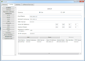
| Step 6: Now we can configure the DHCP server. The first pool is for our local network 192.168.1.0. |
 |
| Step 7: The start ip is 192.168.1.10 with a subnet mask 255.255.255.0. With a maximum of 100 users. So the ip addresses available for the DHCP clients are 192.168.1.10-192.168.110. |
 |
| Step 8: When our DHCP server is configured the port status summary should look like this. |
 |
| Step 9: Now we add a computer in the same local network. For example a laptop and connect it to the switch. |
 |
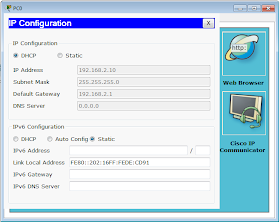
| Step 10: Now change the ip configuration to DHCP. Now our laptop has a ip address provided by the DHCP server. |
 |
| Step 11: To verify our network works you can ping from the laptop to the server. |
 |
| Step 12: We have to create VLAN's on our router. We do this step by step so now we only add our VLAN for the subnet where our server is located. |
 |
| Step 14: We also have to give the VLAN an ip address. You can easily do this in the CLI. The commands you can see in the screenshot. |
 |
| Step 15: After these steps the port status summary should look like this. |
 |
| Step 16: Now we can start building our second subnet, starting by adding a new switch. |
 |
| Step 17: Adding the second subnet to the router. |
 |
| Step 18: Change the port status to on, and the VLAN to the one we just created. |
 |
| Step 20: The basic network is made. By adding a new end device to the new switch we can test our DHCP server. |
 |
| Step 21: But first we need to add an other pool to our DHCP server. This time we need to add the 192.168.2.0 network. |
 |
| Step 23: Now add a third switch and a pc for our third subnet. |
 |
| Step 24: Again we have to add a new subnet in our router. |
 |
| Step 25: Also again configure the ip address and ip helper address. |
 |
| Step 26: Change the "FastEthernet0/1/2" to VLAN200. Again switch the port to on. |
 |
| Step 27: Now add the third subnet to the pool. This time it's network 192.168.3.0. |
 |
| Step 28: Again change the ip configuration to DHCP. Normally your pc will receive an ip address. |
 |
| Step 29: The last subnet is connected with an access point. Add the access point and a wireless device to your network. |
 |
| Step 30: Next we add the last subnet: Subnet4 with number 300. |
 |
| Step 31: Again change the VLAN of "FastEthernet0/1/3". Do not forget to switch the port on! |
 |
| Step 32: Add the network to the DHCP. |
 |
| Step 33: Give the VLAN the ip address 192.168.4.1 with ip helper address 192.168.1.6. |
 |
| Step 34: The tablet should get a ip address from the DHCP server. |
 |
| Step 35: Now simply add more clients to your network. |
Running Config
Over here is the running config of the router:!
version 12.4
no service timestamps log datetime msec
no service timestamps debug datetime msec
no service password-encryption
!
hostname Router
!
!
!
!
!
!
!
!
!
!
!
!
!
!
spanning-tree mode pvst
!
!
!
!
interface FastEthernet0/0
no ip address
duplex auto
speed auto
shutdown
!
interface FastEthernet0/1
no ip address
duplex auto
speed auto
shutdown
!
interface FastEthernet0/1/0
switchport access vlan 10
switchport mode access
!
interface FastEthernet0/1/1
switchport access vlan 100
switchport mode access
!
interface FastEthernet0/1/2
switchport access vlan 200
switchport mode access
!
interface FastEthernet0/1/3
switchport access vlan 300
switchport mode access
!
interface Vlan1
no ip address
shutdown
!
interface Vlan10
ip address 192.168.1.1 255.255.255.0
!
interface Vlan100
ip address 192.168.2.1 255.255.255.0
ip helper-address 192.168.1.6
!
interface Vlan200
ip address 192.168.3.1 255.255.255.0
ip helper-address 192.168.1.6
!
interface Vlan300
ip address 192.168.4.1 255.255.255.0
ip helper-address 192.168.1.6
!
router rip
!
ip classless
!
!
!
!
!
!
!
line con 0
!
line aux 0
!
line vty 0 4
login
!
!
!
end


